


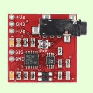
AD8232 ECG Kit
600.00৳
ECG Measurement AD8232 Pulse Cardiac ECG Kit
In stock
Description
An integrated signal conditioning module is available for ECG and other biological electricity measurement applications. The device is designed to extract, amplify, and filter weak biological electrical signals while eliminating noise generated by motion or remote electrodes. The design allows for easy collection of output signals by ultra-low power modulus converters (ADC) or embedded microcontrollers.
To eliminate pseudo-pseudo-image and electrode semi-battery potential, AD8232 employs a bipolar high-pass filter. The filter and the instrument amplifier structure are tightly coupled, which can achieve single-level high-gain and high-pass filtering, thereby saving space and cost. Additionally, an unused computing amplifier is used to create a triode low-pass filter to eliminate additional noise. Users can select the cut-off frequency of all filters to meet the needs of different types of applications.
To enhance the co-mode inhibitory performance of the frequency of the system line and other adverse interference, AD8232 includes a built-in amplifier for the use of the drive (RLD) such as the right side. Furthermore, AD8232 has a fast recovery function, which can reduce the long-tail phenomenon of a high-pass filter. If the amplifier’s orbit voltage occurs, the signal mutation (such as the detachment of the leader), AD8232 will automatically adjust to a higher filter cut-off state. This function allows AD8232 to achieve rapid recovery, so it can obtain effective measurement values as soon as possible after the electrode is connected to the measurement object.
[Plate_number_1] is rated for performance within a temperature range of 0°C to 70°C, with an operating temperature range of -40°C to +85°C.
Applications for AD8232 include fitness and exercise heart rate monitoring, portable ECG, remote health monitoring, game peripheral equipment, and biological telecommunications signal collection.
The pin descriptions are as follows:
- HPDRIVE: Qualcomm drive output. HPDRive should be connected to the capacitance in the first high-pass filter.
- +In: Instrument amplifier input. +In is usually connected to the left arm (LA) electrode.
- −In the Instrument amplifier negative input. It is usually connected to the right arm (RA) electrode.
- RLDFB: Right leg driver feedback input. RLDFB is a feedback pin for the right leg drive circuit.
- RLD: Right leg drive output. The drive electrode (usually the right leg) should be connected to the RLD pin.
- SW: Quickly restored switch to the feet. This pin should be connected to the output end of the second high-pass filter.
- OPAMP+: Computing amplifier input end.
- Refout: Reference voltage buffer output. The output of the instrument amplifier refers to this potential. Refout should be used as a virtual land that needs to reference signals in the circuit.
- OPAMP: Computing amplifier input end.
- OUT: Computing amplifier output end. This output terminal provides a fully-conditioned heart rate signal. OUT can be connected to the input terminal of ADC.
- LOD−: Leader off output end of the comparator. In the DC leader off-detection mode, when connecting to the −In electrode, LOD− is at a high level; otherwise, it is at a low level. In the mode of communication, LOD− is always at a low level.
- LOD+: Leader output of the comparator. In the DC leader off-detection mode, when the +In electrode is turned on and connected, LOD+ is at a high level; conversely, at a low level. In the mode of communication leader, when the −In or +In electrode is turned on and connected, LOD+ is at a high level. These two electrodes are at a low level when they are connected.
- +SENSE: Blind control input end.
- SDN: Drive the SDN to a low level to enter the low power consumption interruption mode.
- AC/DC: Direct current leader off mode controls the input terminal. For the DC leader off, the AC/DC pin should be driven to the low level; for the exchanges, the AC/DC pin should be driven to the high level.
- FR: Quickly restores control input terminal. The high level of the FR driver can enable the mode to recover quickly; otherwise, it should drive it to a low level.
- VDD: Power supply.
- Refin: Reference voltage buffer input. Refine (high-impedance input pin) can be used to set the level of the reference voltage crusher.
- IAOUT: Instrument amplifier output pins.
- HPSENSE: Instruments of Qualcomm detection input. The HPSENSE should be connected to the R and C nodes of the turning frequency of the direct circuit.
- EP: Naked pad. Naked pads should be connected to GND or kept non-connected.
Only logged in customers who have purchased this product may leave a review.
Reviews
There are no reviews yet.